ShapeSource by Visimation is your one-stop source for Visio stencils Visio shapes and Visio templates. You can enter shape data and add new data to a shape.
Microsoft Visio Electrical Stencils Yellowgray
Arduino Visio Schematic Stencil.
Visio schematic shapes. Special Connector Kit makes building in-series and between-series adapters simple. In VIsio go to Shapes - More Shapes - Open Stencil. Right-click the shape and select Data Shape Data.
Most of the stencils are for RF microwave and wireless drawings but a few are included for standard electronic schematics since often the two types are combined. We also take great care not to label them system schematics because a true schematic should take into account the installation architecture which requires in-person inspection and load calculation and a lot of other elements that only an installer should be handling which is probably a lot of the. Free download 53 visio templates example free professional.
Below are some sample shapes for you to download and try out. Browse our eCommerce website for both free and paid stencils for Microsoft Visio 2013 2010 and older versions of Visio for creating professional quality technical drawings maps diagrams schematics and more. Click on the thumbnails for large versions.
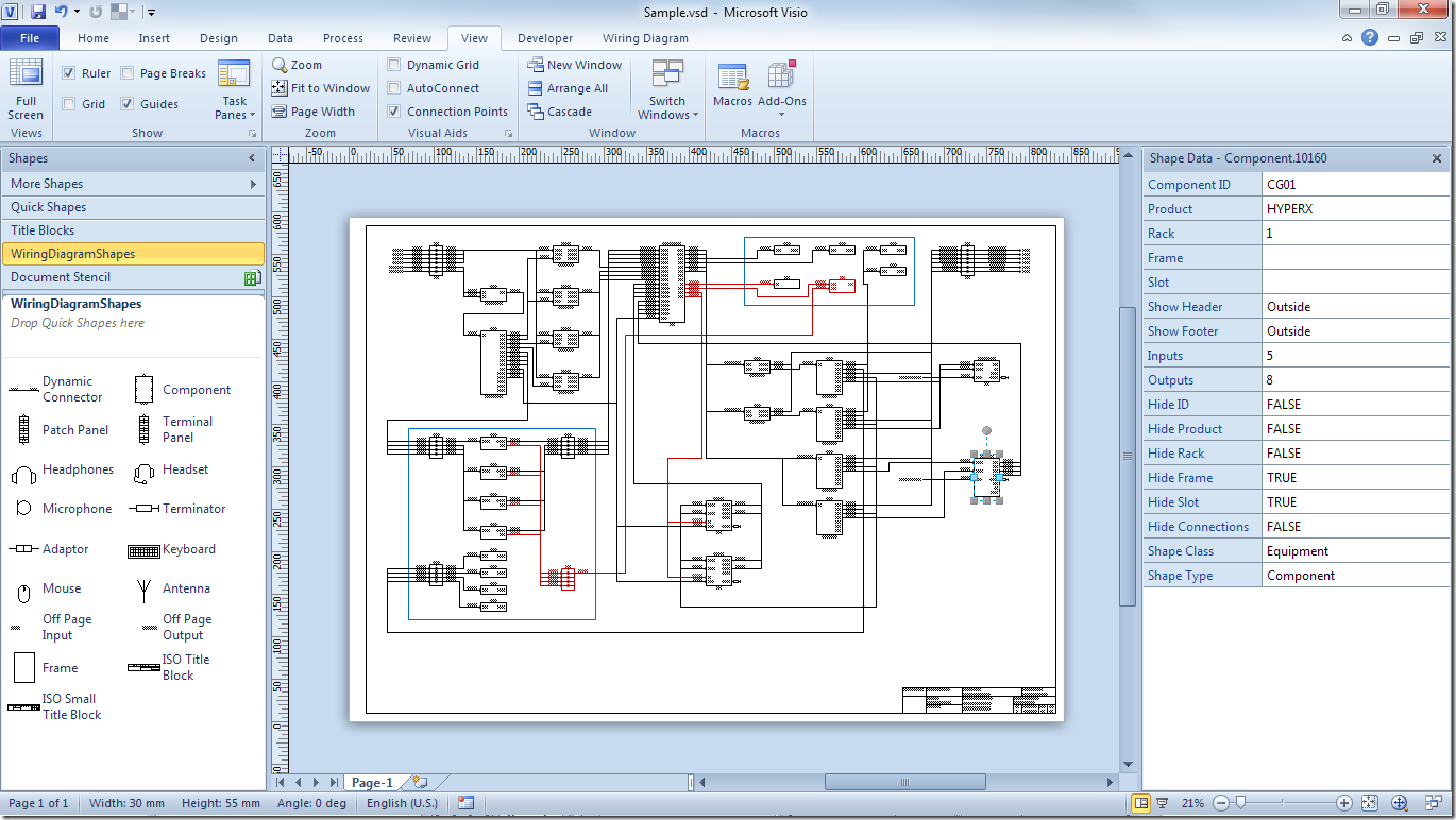
Some of the basic shapes or stencils you would find in a rack are included with the template. Schematic shapes list the inputs and outputs for a device and are located in the Schematic and Line Shapes Stencil. The Electrical Engineering templates in Visio 2003 make it possible to create electrical and electronic schematic diagrams as well as wiring diagrams as Figure 27-8 shows.
To display the Shape Data window click the View tab then select Shape Data from the Task Panes dropdown. Visio has a lot of built-in symbols for electronics. Among other things you can draw integrated circuit and logic circuit schematics general electrical diagrams schematics one-line and wiring industrial control system schematics and printed circuit.
Shapes can have shape data. Rf electronics stencils for visio great concept engineering drawing circuit schematic symbols from block diagrams shapes example microwave link icon 226997. Select a shape right-click click Data and then click Define Shape Data.
Rf Electronics Stencils For Visio Cafe. Our sample Visio templates provide the environment which will contain the specific stencils such as for racks and rows of racks. These are the Shape Data fields for Schematic Shapes.
Starting the Drawing Click the Start button in the bottom left corner of the screen then choose All Apps then V and open Visio 2016 then click on Basic Diagram. ShapeSource by Visimation is your one-stop source for Visio stencils Visio shapes and Visio templates. Schematics should be per-installation since every system is a little different.
Includes the Arduino UNO and the basic shapes from the Electronic Brick Starter Kit. The block diagram at the right is an example of what can be done with the new symbols. Among other things you can draw integrated circuit and logic circuit schematics general electrical diagrams schematics one-line and wiring industrial control system schematics and printed circuit.
A simple Visio stencil that you can easily add to your My Shapes folder to save time when drawing your schematics. So that you can create BOM. Browse our eCommerce website for both free and paid stencils for Microsoft Visio 2013 2010 and older versions of Visio for creating professional quality technical drawings maps diagrams schematics and more.
The text for these shapes like most of the Visio SI shapes are aware of the background color and the text will automatically change from black to white based on the color choice. Interconnecting wire routes may be shown approximately where particular receptacles or fixtures must be on a common circuit. Hold your mouse over one of the arrows and a mini toolbar will appear with the top four shapes in the Quick Shapes area.
Choose a shape and drag it onto the canvas to add it to your diagram. AV Designer Seeks Current Visio Schematic StencilsShapes Ive recently started designing AV systems and need some help finding schematic stencilsshapes to use in Visio 2016 for products from Crestron Extron Cisco etc. Shapes can have data.
Go to the Shapes window. How to create a Visio smart shape representing a three-input AND gate. Architectural wiring diagrams do its stuff the approximate locations and interconnections of receptacles lighting and unshakable electrical facilities in a building.
721 Visio shapes and symbols in 39 Visio stencils in both US units and metric units all in Visio VSS VSX VSSX and VSDX formats for creating your electronic circuit diagrams in Visio. Below are screen captures of all the stencil sets provided with RF Electronics Schematic Block Diagram Stencils for Visio r4. By default each InputOutput lists the Terminal Signal and Label fields.
Find More Shapes And Stencils. For the Schematic shapes you can now right click or use the Shape Data UI to choose from the standard Si Color pallet. In the Shape Data pane click in each data field and type or select a value.
Rf Connector Layout Design Visio Stencil Sets Shapes Free Stencils Templates Add Ons Shapesource. Creating from scratch is too time consuming. Download Sample Visio Templates.
Navigate and open this file replace OfficeXX with the appropriate folder CProgram Files x86Microsoft OfficeOfficeXXVisio Content1033EEvss. The Electrical Engineering solutions in Visio 2002 make it possible to create electrical and electronic schematic diagrams as well as wiring diagrams as Figure 27-8 shows. Most of the shapes have custom properties ShapeData for manufacturer data part numbers etc.
You can enter shape data and add new data to a shape. The most common used settings can also be accessed by right-clicking the Shape. Please check the NOTES section on this page for instructions andor any updates.
You should see a Shapes window on the left. This video will demonstrate creating a Visio Schematic drawing in SI 2016Support page. Once youve chosen your template its time to start adding shapes to your Visio schematic drawing.
Schematic The default Schematic shape displays the Inputs and Outputs for the product based on what has been entered in the IO Studio. Drag electrical component shapes onto the drawing page. In the Define Shape Data dialog box click in each item and type or select a value.

Making A Circuit In Visio How To Ep 34 Youtube
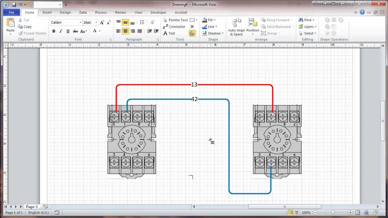
Visio 2010 Connectors And Connection Points Tutorial Wiring Diagrams Youtube